Bob,
Just getting to this post...
Here are some comments on the couplers on our SDSU rocket
<http://eon.sdsu.edu/%7Erocket/>:
1. Our SDSU rocket was 8" diameter, 0.072" wall.
2. The coupler was made from the same tube; we slit the tube
longitudinally to remove enough so that it could be fit into the
original 8" tubing.
3. We riveted the coupling to the airframe/tank tube for sections
that we did not intend to seperate.
4. For sections we wanted to separate we used twenty (20) 8-32
screws. We had a few screws strip in the thin 0.072" wall, so your
method with inserts is appealing.
5. Our big problem was alignment of airframe sections, which many on
this list gave some good tips.
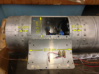
6. Picture of our inter tank adapter here
<http://4.bp.blogspot.com/-y9c5oqkLSw4/URW_PgeNrnI/AAAAAAAAAFc/Wpq8c8LMobA/s320/Rocket+project+1.jpg>
7. An HPR guy once told me to make the coupler insertion length at
least one caliber. We did not follow that advice and hence could
have contributed to our alignment issues given the tolerances of
our "rolled" couplers.
Why could you not use your "inner sleeve" as the coupling tube? Seems
like one extra part.
Richard Nakka has a nice little webpage on calculating loads on your
airframe here <http://www.nakka-rocketry.net/fusestru.html>. It
doesn't address loads at if your rocket has any angle-of-attack, but
it's still a nice guide.
--- Carl

On 10/11/2013 2:23 PM, Robert Watzlavick wrote:
I'm designing the couplings that will connect each of the propellant
tanks to the rest of the structure for my rocket. The primary
structure for the tanks is 5 inch OD, 0.125 wall 6061-T6 tubing. The
question is: what wall thickness and length does the coupling tube
need to be to connect two of the 5 inch OD tubes together? To
simplify the discussion, ignore the tank bulkheads or any other
structure for now. I don't have an estimate yet of the expected
flight bending loads but for a first pass, one philosophy would be to
make the joint at least as strong as the rest of the structure in
bending so it won't fail at the joint. There would actually be 3
concentric elements: 1) the two primary structure elements butted up
end-to-end, 2) the coupling sleeve inside, and 3) another sleeve
inside the first one. NAS 623 fasteners, installed radially from the
outside in are used to hold it all together, with the primary
structure and coupling sleeve drilled to match the "grip" diameter of
the fastener. The only purpose of the inner-most sleeve is to have
something for the fastener to thread into. By using a second sleeve,
there are no shear loads on the fastener threads, only tension.
Even though the inner sleeve (with fastener threads in it) will
provide additional stiffness, I wasn't going to count its
contribution since it will be cut down as thin as possible. The
material for the two sleeves would also be 6061-T6.
If the goal is to match the bending capability of the primary
structure, then I would think the coupling sleeve only needs to be
thick enough to match the moment of inertia of the primary
structure. Then, the length of the coupling should only be a
function of the shear tearout allowable for the joint. Am I on the
right track here? Of all the allowables for the joint (fastener
shear stress, bearing stress, shear tearout, net area tension), shear
tearout and bearing stress appear to be the most critical for this
design. One thing I'm not sure about is how to convert an arbitrary
bending moment into the shear load per fastener.
See attached sketch for details.  Any advice would be appreciated.

-Bob
--
Carl Tedesco
Flometrics, Inc.
5900 Sea Lion Place, Suite 150
Carlsbad, CA 92010
tel: 760-476-2770 ext. 515
fax: 760-476-2763
ctedesco@xxxxxxxxxxxxxx
www.flometrics.com
