[AR] Re: Intertank coupling design
- From: Ben Brockert <wikkit@xxxxxxxxx>
- To: "arocket@xxxxxxxxxxxxx" <arocket@xxxxxxxxxxxxx>
- Date: Tue, 29 Oct 2013 15:48:05 -0600
Bringing 6061 tanks up to T6 is a pain in the ass because it involves
solution annealing, which requires getting the tank frighteningly close to
melting and then quenching rapidly with water or a lot of cool gas. Doing
it without collapsing or warping the tank requires careful setup and
skilled operators. The tank can be straightened after the quench, but that
requires another, possibly complex, setup.
Instead, skipping the solution anneal and going straight to artificial
aging can give you results of 6061-T5, without nearly as much hassle. It's
an improvement of about 50% in tensile strength. It just requires an oven
that the part can fit in, which for tanks those size could probably be done
at a powder coating shop. There are a lot of different formulas for
artificial aging, usually two heats of two to eighteen hours each, at
temperatures between 300 and 400F. Higher temperatures take shorter times;
normal aging would be to let the part sit at a warmish room temperature for
a year or two.
Still well short of the state of the art in 6000 series rocket tanks but a
useful and achievable improvement over as-welded condition.
Ben
On Tue, Oct 29, 2013 at 2:56 PM, Carl Tedesco <ctedesco@xxxxxxxxxxxxxx>wrote:
> No heat treating was performed. I would have liked to, but budget
> wouldn't allow it. We did hydro test the complete welded tanks to 450 psi
> for 5 complete pressurize/depressurize cycles (MEOP 350 psi).
> --- Carl
>
>
> On 10/29/2013 12:18 PM, Paul Mueller wrote:
>
> Carl,
>
> Wow, beautiful work! Did you heat-treat the tanks to T6 after welding or
> were they strong enough as is?
>
> Paul M
>
>
> On Tue, Oct 29, 2013 at 10:26 AM, Carl Tedesco
> <ctedesco@xxxxxxxxxxxxxx>wrote:
>
>> The end caps were hydro-formed from 1/8" thick 6061-T0 aluminum using a
>> paint sprayer to generate the high pressure required to deform the domes.
>> We were trying to make the ends as close to 2:1 elliptical domes, but in
>> reality they came out as a spherical segment about 2" tall. We machined
>> them to a perfect 8" diameter then butt welded them to the seamless 8"
>> diameter tube. We then added an additional 4" section of the 8" tube to act
>> as a tank skirt.
>>
>>
>>
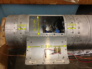
>> Here's an inter-tank adapter with an access hatch:
>>
>>
>> We routed all plumbing and electrical lines outside the tanks and made a
>> fiberglass faring. Here are a few pics of the faring:
>>
>>
>> https://www.facebook.com/photo.php?fbid=525688197501822&set=pb.287398957997415.-2207520000.1383063222.&type=3&theater
>>
>>
>> https://www.facebook.com/photo.php?fbid=525689307501711&set=pb.287398957997415.-2207520000.1383063220.&type=3&theater
>>
>> --- Carl
>>
>>
>>
>>
>> On 10/28/2013 7:39 PM, Robert Watzlavick wrote:
>>
>> Carl,
>> Since your tanks were also part of the airframe, how did you handle the
>> tank end caps? What was the shape and were they welded? Also, did you
>> route cables and feedlines through the tanks or around the outside?
>>
>> -Bob
>>
>> On 10/25/2013 02:04 PM, Carl Tedesco wrote:
>>
>>
>>
>> Sent from my iPhone
>>
>> On Oct 24, 2013, at 8:47 PM, Robert Watzlavick <rocket@xxxxxxxxxxxxxx>
>> wrote:
>>
>>
>> Carl,
>> Thanks for the info and link to Richard's page. I haven't decided on the
>> exact coupler configuration yet so there's still room to improve the
>> design. I assume one "caliber" means one diameter?
>>
>>
>> Yes, one caliber = one diameter.
>>
>> I saw that on many other HPR websites where the construction materials
>> were composites or fiberglass. Some of them even suggested two or three
>> diameters. I can't believe that you would need a 5-10 inch long coupler to
>> hold two 5 inch diameter tube sections together.
>>
>>
>> In hindsight, they may be talking about the sections that separate for
>> parachute deployment, since these sections usually have 2 to 4 nylon shear
>> screws. The one caliber rule insures the section stays put during high
>> speed flight.
>>
>> An airplane fuselage is many feet in diameter and they usually only
>> have a single frame section with a few inches on either side. Of course
>> there stringer section running the length of the airplane.
>>
>>
>> Ours was about 2-3 inch long coupler for our 8-inch diameter airframe. If
>> I do it this way again I would probably use two rows of fasteners offset;
>> still the same number of fasteners.
>>
>> I can envision alignment issues though, especially if the ends aren't
>> completely round and the fastener holes aren't drilled perfectly square to
>> the ends. I was hoping to mitigate some of that by making the coupler a
>> bit thicker than needed so it wouldn't deform as everything is bolted
>> together.
>>
>> Was your fuselage skin also the pressure tank?
>>
>>
>> Yes, the pressurized tanks were also the airframe.
>>
>> ---Carl
>>
>>
>> I had to go with 16 #10-32 screws on the 5 inch diameter to keep from
>> exceeding the bearing allowable stress on the skin. With a conservative
>> 2.0 factor of safety, the tank end caps have to withstand around 18000 lbf
>> each (which works out to about 1100 lbf per #10 fastener in shear).
>>
>> -Bob
>>
>> On 10/23/2013 02:17 PM, Carl Tedesco wrote:
>>
>> Bob,
>> Just getting to this post...
>>
>> Here are some comments on the couplers on our SDSU
>> rocket<http://eon.sdsu.edu/%7Erocket/>
>> :
>>
>>
>> 1. Our SDSU rocket was 8" diameter, 0.072" wall.
>> 2. The coupler was made from the same tube; we slit the tube
>> longitudinally to remove enough so that it could be fit into the original
>> 8" tubing.
>> 3. We riveted the coupling to the airframe/tank tube for sections
>> that we did not intend to seperate.
>> 4. For sections we wanted to separate we used twenty (20) 8-32
>> screws. We had a few screws strip in the thin 0.072" wall, so your method
>> with inserts is appealing.
>> 5. Our big problem was alignment of airframe sections, which many on
>> this list gave some good tips.
>> 6. Picture of our inter tank adapter
>> here<http://4.bp.blogspot.com/-y9c5oqkLSw4/URW_PgeNrnI/AAAAAAAAAFc/Wpq8c8LMobA/s320/Rocket+project+1.jpg>
>> 7. An HPR guy once told me to make the coupler insertion length at
>> least one caliber. We did not follow that advice and hence could have
>> contributed to our alignment issues given the tolerances of our "rolled"
>> couplers.
>>
>> Why could you not use your "inner sleeve" as the coupling tube? Seems
>> like one extra part.
>>
>> Richard Nakka has a nice little webpage on calculating loads on your
>> airframe here <http://www.nakka-rocketry.net/fusestru.html>. It doesn't
>> address loads at if your rocket has any angle-of-attack, but it's still a
>> nice guide.
>>
>> --- Carl
>>
>>
>>
>> --
>> Carl Tedesco
>> Flometrics, Inc.
>> 5900 Sea Lion Place, Suite 150
>> Carlsbad, CA 92010
>> tel: 760-476-2770 ext. 515
>> fax: 760-476-2763ctedesco@xxxxxxxxxxxxxxxxxxxxxxxxxxxxxxxx
>>
>>
>
> --
> Carl Tedesco
> Flometrics, Inc.
> 5900 Sea Lion Place, Suite 150
> Carlsbad, CA 92010
> tel: 760-476-2770 ext. 515
> fax: 760-476-2763ctedesco@xxxxxxxxxxxxxxxxxxxxxxxxxxxxxxxx
>
>


Other related posts:
